To enable the holes and/or grooving fields on a panel, click on the “Show Holes” and “Show Grooving” check boxes in the bottom right of the panel window.
Specifying Holes
Holes positions are specified relative to the side that you are specifying them on:
Length 1 = Starts from the bottom left corner of a non-rotated panel
Length 2 = Starts from the top right corner of a non-rotated panel
Width 1 = Starts from the top left corner of a non-rotated panel
Width 2 = Starts from the bottom right corner of a non-rotated panel
Refer to the image below while reading about the different ways of specifying a hole:
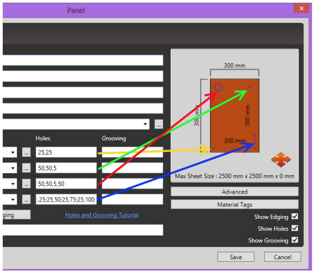
Simple Format “x,y”
The simplest way to specify holes on a panel is to provide a x and y co-ordinate. The depth of the hole and the diameter of the hole will then be assumed by using the values specified in your settings. For example: 25,25. (Indicated by the yellow arrow in the image above)
Full Format “x,y,depth,diameter”
The full format used to specify a hole is: x,y,depth,diameter. For example: 50,50,5,50 specified on Width 1 will draw a hole 50 down and 50 across from the top left corner at a depth of 5 and a radius of 50. (Indicated by the red arrow in the image above)
Partial Format “x,y,depth”
The diameter can also be omitted from the syntax: x,y,depth. For example: 50,50,5. In this case the default diameter will be used. (Indicated by the green arrow in the image above)
Specifying Multiple Holes on one side
Multiple holes can be specified on the same side, each hole must be separated by a semi-colon “;”. For example: 25,25;25,50;25,75;25,100 will specify 4 holes. (Indicated by the blue line in the image above)
Mixing syntax
When specifying multiple holes, any combination of the described syntax’s is acceptable. For example 25,25;70,70,7;130,130,13,100 will result in 3 holes: Hole 1: “25,25” = 25 on the x axis and 25 on the y axis relative to the corner, with the default depth and diameter. Hole 2: “70,70,7” = 70 on the x axis and 70 on the y axis relative to the corner, with a depth of 7 and the default diameter Hole 3: “130,130,13,100” = 130 on the x axis and 130 on the y axis relative to the corner, with a depth of 13 and a diameter of 100.
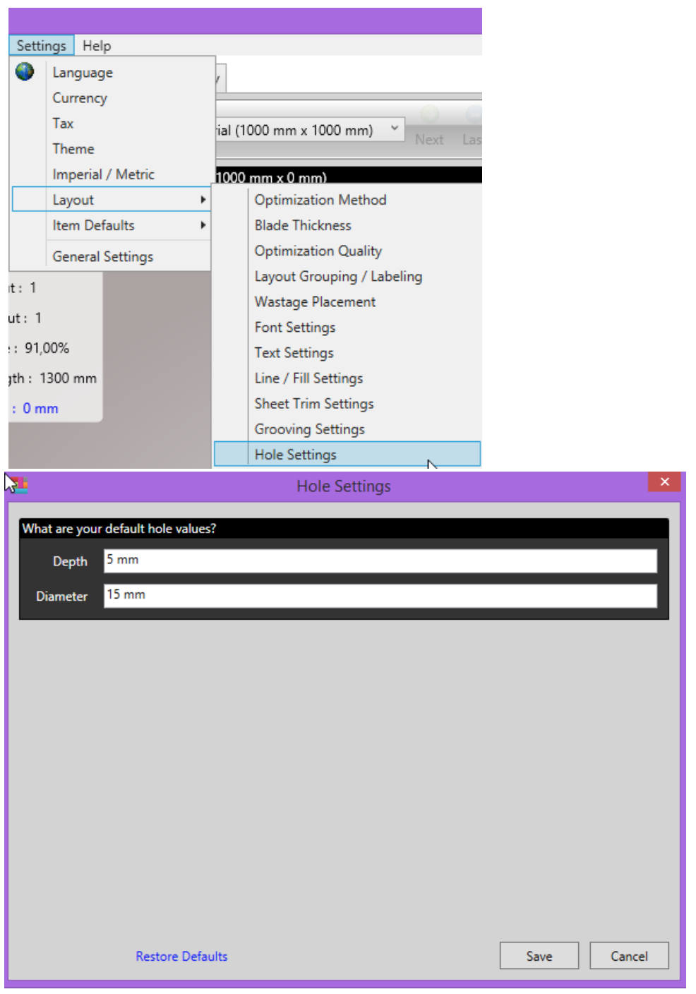
Configuring Defaults
Default values can be set by going to Settings -> Layout -> Hole Settings
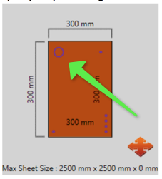
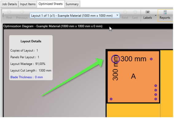
Results
Holes will show on the relevant previews and reports.
The panel preview diagram when adding a panel and on the screen optimization layout and layout reports.
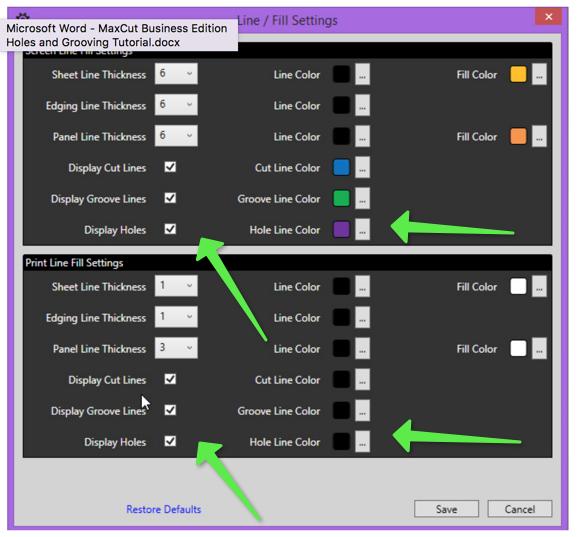
Changing How Holes Are Displayed
The display of holes can be turned on or off and the color in which it is displayed can be
changed by going to “Settings -> Layout -> Line / Fill Settings”. As shown in the image below.
Comments
1 comment
Are we going to have holes each count in mm
for example:
5 equal holes on the length of the panel
or each 96mm hole diameter = 20mm
Please sign in to leave a comment.